The
Genesis Of
Vinyl
Stereo Record.
Updated
2011-12-08
(Vinyl
Remastering)
by
Rolf Badenhausen
Die
Entstehungsgeschichte
der
Stereoschallplatte
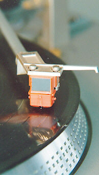
The first Westrex stereo recording cartridge of 1958.
|
| Already
in 1954 high requirements for audio reproduction were discussed in the
USA for improving the existing High Fidelity standard: The
Radio Designer's Handbook (Langford-Smith) was referring
to a frequency
response of 30 Hz to 20 kHz at a linearity required ± 0,1 dB!
For
this ambitious aim to better performance, the distortion factor was
proposed
to be less than 0.5 % (THD) at an S/N ratio of not less than 62 dB.
In
principle, any three-dimensional media does offer the independent
degrees
for a simple analogue stereo recording, e.g. height and width for the
amplitude
of both channels, and length for time. However, it's the little things
(or just different ways of thinking) that always cause the
problems.
A.D.
Blümlein had developed a Single Groove Stereo disk for British
E.M.I.
(Electrical & Musical Industries) already in 1933, certified as
British
Patent No. 394 325. Later on, he continued with his work for making an
improved record system at Columbia Records in the USA. There, and also
in some European countries, the first stereo disks were introduced in
summer
1958.
At
the beginning of that year, a German- English prototype had been even
competing
with an American version for the definite standard: The London Record
Co.,
inspired by an idea of German Telefunken company, was pushing a
rectangular
cutting method for both channels, shortly called "+", while Westrex
Inc.,
New York, was favouring a diagonal one, the "45/45" or "x".
|
|
Bereits
im Jahr 1954 wurden in den USA hohe Anforderungen zur Anhebung der dort
vorherrschenden HiFi- Qualitätsmaßstäbe diskutiert: Im
Radio
Designer’s Handbook (Langford-Smith) war für einen
anzustrebenden
Frequenzbereich von 30 Hz bis 20 kHz eine Linearitätstoleranz von
± 0,1 dB genannt worden! Für dieses ehrgeizige Ziel sollte
der Klirrfaktor höchstens 0,5 % sowie der Geräuschabstand
mindestens
62 dB betragen.
Grundsätzlich
bietet jedes dreidimensionale Medium die Freiheitsgrade für eine
einfache
analoge Stereo-Aufzeichnung, z. B. Höhe und Breite für die
Amplitude
beider Kanäle sowie die Länge für die Zeit. Jedoch
steckt
auch hierbei der Teufel im Detail...
A.D.
Blümlein hatte bereits 1933 eine einspurige Stereoschallplatte
für
das britische E.M.I. Unternehmen entwickelt (British Patent No. 394
325).
Er setzte seine Arbeiten zur Schaffung eines verbesserten
Aufzeichnungsverfahrens
später bei Columbia Records in den USA fort. Dort, wie auch in
einigen
europäischen Ländern, wurden die ersten Stereo-LPs im Sommer
1958 eingeführt.
Noch
zu Beginn jenes Jahres hatte ein deutsch- englischer Prototyp mit einer
amerikanischen Version um jene endgültige Norm konkurriert: das
von
der London Record Co. nach einer Telefunken- Idee vorangetriebene
„Tiefe/Seite“-Verfahren
(Kürzel „+“) mit dem von der Westrex Inc., New York, favorisierten
Diagonalverfahren „45/45“ bzw. „x“.
|
|
|
|
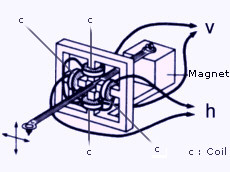
Fig.1.1
v: vertical output h: horizontal output
|
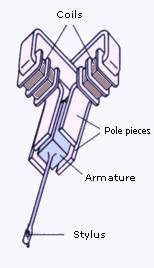
Fig.
1.2 Pickup system with magnetic
armature.
|
The
recording system as developed by London Record Co. represents Fig. 1.1.
Westrex Inc. had taken over this system in principle, but turned it to
a 45 degree position. Naturally, the position of the stylus,
respectively
its axis, was turned back perpendicularly. This x system does guarantee
equal mechanical and electrical properties for both channels, while the
vertical channel of the "+" will be recognized problematical for
distortion,
and the horizontal for stylus force and clamping.
Thus,
the x-Method became world standard in the end.
Fig.
1.2 shows a realization of 1.1: An industrial pickup with moving
armature (respectively moving magnet) that is widely known as MM
type.
Crosstalk
suppression for audio reproduction should not fall below 20 dB in
accordance
with the first standard. A measure of 30 dB (typical at that time) does
mean an angular deviation below 1.5 degree for the stylus, respectively
an error deflection of less than 0.04 µm at 10 kHz! However,
suppression
better than 40 dB was achieved later on.
Regarding
a basic effect of mono as well as stereo disk recording, there will be
an enormously increasing stylus deflection for low frequencies, as
shown
by this equation:

a Stylus Deflection
s Stylus
Rapidity
(const.)
 Angular
Signal Frequency Angular
Signal Frequency
Therefore,
appropriate signal compression will be necessary for an acceptable disk
capacity!
Appendix
A gives detailed information about almost all different standards
for
decompressing equalization. This data was published in 1958. Both 'RCA
Victor' and 'TELDEC' were applied to stereo disks. The RCA Victor
standard,
"New Orthophonic", advanced to RIAA
Equalization Definition .
.
|
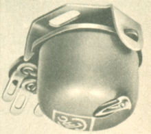
Fig.
1.3 .[4]
1958:
One
of Europe's first magnetic stereo pickups:
The
Pot of ELAC: STS 200.
Eines
der ersten Magnetsysteme in Europa.
Fig.
1.4 [5]
| Top
diagram is based on thoroughly made tests with micro groove disks at
the
end of the Fifties. It shows the downfall of upper cutoff frequency
versus
grinding of sapphire stylus 'Abschlifflänge', given in µm.
The
smaller diagram informs about durability (in hours) of sapphire stylus
for stereo or 'duplo' and mono systems. |
| Nach
gründlichen Untersuchungen gegen Ende der 50er Jahre wurden
für
Mikrorillenplatten der Einfluss der Saphir- Abnutzung auf die obere
Grenzfrequenz
(oben) und die zu erwartende Spieldauer (unten) für Stereo-
"Duplo-"
und Monosysteme ermittelt. |
|
Das
von der London Record Co. entwickelte Aufzeichnungsverfahren
verdeutlicht
die Prinzipdarstellung des in Fig. 1.1 gezeigten Tonabnehmers. Die
Westrex
Inc. hatte diese Anordnung im Prinzip übernommen, drehte diese
jedoch
einfach um 45° Grad. Um den gleichen Betrag zur Senkrechten wurde
selbstverständlich
die Abtastnadel bzw. deren Achse wieder zurück gedreht. Dieses x-
System garantierte für beide Kanäle gleiche mechanische wie
elektrische
Eigenschaften. Dagegen erkannte man beim "+" Probleme für den
vertikalen
Kanal wegen Verzerrungsanfälligkeit sowie ungünstigem
Nadeldruck-
und klemmungsverhalten für den horizontalen. Damit setzte sich das
X- Schneidverfahren als Weltstandard durch.
Fig.
1.2 zeigt eine Realisation nach Fig. 1.1. Jene Ausführung stellt
einen
industriell gefertigten Tonabnehmer dar, und zwar mit beweglichem
magnetischen
Anker (armature), feststehenden Polschuhen (pole pieces) und den Spulen
(coils). Alle gängigen MM-Tonabnehmer („Moving Magnet“) liegen
diesem
Ausführungsbeispiel zugrunde.
Die
Übersprechdämpfung für Wiedergabebetrieb sollte
gemäß
dem ersten Standard 20 dB nicht unterschreiten. Das damals übliche
Maß von 30 dB bedeutet einen Winkelfehler von unter 1,5 Grad
für
den Stichel, bzw. eine Fehlauslenkung von weniger als 0,04 µm bei
10 kHz! Allerdings wurden noch Dämpfungswerte oberhalb 40 dB
später
erzielt.
Grundsätzlich
gilt sowohl für Mono- als auch Stereoaufzeichnungen, dass für
niedrige Frequenzen die Nadelauslenkung in beachtlicher
Größenordnung
zunehmen würde, und zwar nach dieser Gleichung:
a Nadelauslenkung
s Nadelschnelle (const.)
Signal-Kreisfrequenz
Daher
ist für eine befriedigende Spielkapazität eine angemessene
Signalkompression
erforderlich!
Anhang
A liefert detaillierte Informationen über nahezu alle
unterschiedliche
Normen zur Signaldekompression bzw. -entzerrung, wie publiziert im Jahr
1958. Sowohl der von RCA Victor eingesetzte Standard als auch der von
TELDEC
wurden für Stereoplatten angewendet. Der erstgenannte, auch als
"New
Orthophonic" zitiert, setzte sich durch zur
RIAA-
Entzerrungskennlinie .
.
|
| . |
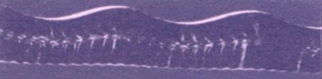
Fig.
1.5
A
Stereo Groove – eine Stereo-Rille.
Left
channel: 1000 Hz Sinus Signal - linker Kanal
Right
channel: 12 000 Hz Sinus Signal - rechter Kanal
Top
of this image to the disk's centre. Photo released by Dutch RONETTE
company
[1].
Der
obere Bildrand der von RONETTE (NL) stammenden Aufnahme [1] weist zur
Plattenmitte.
|
. |
.
|
Geometrical
and
Physical Relations and Problems
|
|
Geometrische
und
physikalische Verhältnisse und Probleme
|
.
| Grooves
Fig.
1.6 gives a geometrical impression of the different disk standards. The
'Mono' size, known as 'Normal' (e.g. 'N78' for a disk of 78 r.p.m.) was
predecessor of the monophonic 'Micro' that should be finally
replaced
by stereo standard.
The
minimum groove width was reduced from 55 µm (Micro) to 40
µm
for stereo standard. The radial distance from groove to groove will be
about 120 µm at an average signal level for both channels.
A
stereo pickup can be also used for playing mono disks (Micro standard),
but a mono one would damage a stereo groove within a short time.
Pinch
Effect
Since
the cross- sectional shape of the recording stylus is a 90- degree-
triangle,
pinch effect will come into appearance for large groove amplitudes
at
high frequencies. Fig. 1.7 demonstrates the outcome of this effect: A
and
B represent shape and position of recording stylus that will cause
differential
groove width. Thus, a spherical or conical stylus can only handle this
precondition by a vertical compensatory movement (see C & D) which,
however, will put a disadvantageous effect on total distortion.
Therefore,
about 1963 or 1964, the biradial or elliptical stylus has been
introduced
to successfully elude this problem, cf. E & F, and reduce
distortion
caused by Clamping Effect (s. Appendix B).
Skating
Since
the groove for stereo standard has been geometrically sized down, there
are to consider even other physical effects which had been neglected
for
mono disk players or 'turntables': The vertical stylus force must be
well
adjustable for lower scales. Moreover, an additional mechanical system
must compensate horizontal skating. This effect was going to play a
very
important role for gradually reduced stylus force. Fig. 1.8
explains
in detail.
Trackability
Best
reproduction of high frequencies requires lowest effective stylus mass
(m) at lowest force. Therefore, highest compliance (c) of stylus
rod will be needed. Both quantities define resonant frequency of the
pickup:
where
is angular resonant frequency [3]. Its influence on low frequencies
range
can be taken from Fig. 2.6 of document VSR1Pickups.htm
that has been linked farther below.
.
|
|
Fig.
1.6 [11]
|
|
Size
relations of different record standards.
|
|
Basic
diameter of stereo stylus: ~ 30 µm
|
|
for
stereo groove that has 45 degree sides..
|
|
Größenrelationen
unterschiedlicher Formate
|
|
mit
vorzitiertem Durchmesser der Stereo-
|
|
Abtastnadel
für 45°-Rillenflanken.
|
Fig.
1.7
Emergence
of the Pinch Effect.
Entstehung
des Pincheffekts.
Fig.
1.8.
Emergence
of the Skating Effect.
Entstehung
des Skating Effekts.
|
Plattenrillen
Fig.
1.6 vermittelt einen geometrischen Eindruck der verschiedenen
Standards.
Das Mono- Format, als Normal- Format bekannt mit z.B. N78 für eine
Schallplatte mit 78 Umdrehungen pro Minute, war Vorläufer des
monophonen
"Micro", das schließlich durch das Stereoformat ersetzt wurde.
Die
minimale Rillenbreite wurde von 55 µm (Micro) auf 40 µm
für
den Stereo- Standard reduziert. Der Radialabstand von Rille zu Rille
beträgt
etwa 120 µm bei einem durchschnittlichen Stereosignal- Pegel.
Ein
Stereo- Tonabnehmer kann auch zum Abspielen von Mono- Platten (Micro-
Format)
verwendet werden, aber ein Mono-Abnehmer würde eine Stereorille
innerhalb
kurzer Zeit zerstören.
Pinch
Effekt
Der
Schneidstichel stellt in seiner Querschnittsform ein Dreieck mit
einem 90° Winkel dar. Wegen dieser Form treten bei großen
Rillenauslenkungen
und höheren Frequenzen Rilleneinschnürungen auf, der sog.
"Pincheffekt",
welcher anhand Fig. 1.7 erklärt wird. Darin stellen A und B Form
und
Position des Schneidstichels dar, wodurch sich für die
vorgenannten
Auslenkungen diese besondere Abweichung für die Rillenbreite
erklärt.
Eine sphärische bzw. konische Nadel kann eine solche Vorbedingung
aber nur durch vertikale Ausgleichsbewegungen bewältigen (s. C u.
D), welche jedoch einen nachteiligen Einfluss auf die Gesamtverzerrung
ausüben. Deswegen wurde um 1963/64 die biradiale bzw. elliptische
Nadel eingeführt, welche dieses Problem erfolgreich umgeht (s. E
u.
F) und Verzerrungen durch den Klemmeffekt (s. Anhang B) reduziert.
Skating
Da
man die Rille für das Stereoformat geometrisch verkleinerte, hatte
man noch andere physikalische Effekte zu berücksichtigen, die bei
den bislang gebräuchlichen Mono- Plattenspielern kaum eine Rolle
spielten:
Die Nadel- Auflagekraft musste für nun kleinere
Größenordnungen
gut einstellbar sein. Außerdem musste eine zusätzliche
Konstruktion
das sog. Skating (Querkrafteinwirkung auf Rillenflanke) kompensieren.
Dieser
Effekt war von besonderer Bedeutung für die immer weiter
reduzierte
Nadel- Auflagekraft. Fig. 1.8 verdeutlicht das Skating.
Abtastfähigkeit-Trackability
Die
bestmögliche Wiedergabe von hohen Frequenzen erfordert
grundsätzlich
die geringste effektive Nadelmasse m bei geringster Auflagekraft. Damit
besteht zugleich die Forderung nach höchster Compliance c
(Nadelnachgiebigkeit).
Beide Größen definieren die Resonanzfrequenz des
Tonabnehmers:
worin
die Resonanzkreis- frequenz bezeichnet [3]. Deren Einfluss im
Tieftonbereich
kann Fig. 2.6 im Dokument VSR1Pickups.htm
entnommen
werden, das weiter unten verlinkt wurde..
|
| Tone
Arms
The
recording stylus will follow a straight line from rim to the disk's
centre.
However, the reproducing stylus of a conventional pickup arm does leave
an arc on its way to the groove's end. Turntable designers were facing
this problem by making arms of special geometry, for example S- formed
versions or expensive tangential constructions.
Dynagroove
In
1963, RCA Victor Studios of New York, in association with David Sarnoff
Research Center of Princetown, USA, introduce 'Dynagroove'. This is
sophisticated
recording system for reduction of groove distortion that comes up when
the stylus cannot correctly follow critical groove sections. The
complete
set includes a computer which does filter all those sections, re-
calculates them, and counter- controls accordingly the recording
stylus.
German distributor of those disks was TELDEC company [8].
Dynaflex
In
1971, RCA Corporation announces "big invention" that will enormously
reduce
surface noise (especially so- called 'ticking'), slippage, and other
non-
homogeneous properties of conventional LP disks. For field testing,
more
than 12 million Dynaflex Disks had been already put into circulation in
the previous year.
This
more flexible disk has a compound that does guarantee also much better
durability as well as much smoother grooves for (almost) imperceptible
noise. The disk's thickness was reduced from 50 to 30 mil in its groove
area, and its weight from 135 to 90 grams. Experts confirm this as big
step in development [9], [10].
Final
Results
Considering
all mechanical and electrical points of view for most efficient
technical
solutions, there have been statements that "a high quality turntable
with
a first class cartridge will leave no provable signs of wear on good
vinyl
disks made in the Seventies or later."
|
|
Tonarme
Der
Schneidstichel beschreibt eine Gerade vom Plattenrand zur -mitte.
Dagegen
hinterlässt ein herkömmlicher Tonarm eine bogenförmige
Spur.
Die Konstrukteure von Plattenspielern begegneten diesem Problem mit
besonderen
Tonarmen, z.B. S-förmigen oder aufwendigen Tangential-
Ausführungen.
Dynagroove
Im
Jahr 1963 stellen die RCA Victor Studios in Zusammenarbeit mit dem
David
Sarnoff Research Center in Princetown, USA, das "Dynagroove"
Schneidverfahren
vor. Dieses hochentwickelte System reduziert die von der
Rillenaussteuerung
herrührenden Verzerrungen. In diese Entwicklung war ein Prozess-
Rechner
miteinbezogen, der die kritischen Rillenpassagen herausfilterte, neu
berechnete
und den Schneidstichel entsprechend gegensteuerte. Der Plattenvertrieb
in Deutschland lag bei der TELDEC [8].
Dynaflex
Im
Jahr 1971 kündigt die RCA Corp. eine große Erfindung an,
welche
das Oberflächenrauschen, insbesondere das sog. Tickern, den
Schlupf
sowie andere Unregelmäßigkeiten in der Zusammensetzung der
herkömmlichen
LPs gravierend reduzieren soll. Im voran gegangenen Jahr wurden im
Feldversuch
über 12 Millionen Dynaflex- Platten in Umlauf gebracht.
Die
Zusammensetzung dieser wesentlich biegsameren Platte garantiert sowohl
höhere Lebensdauer als auch deutlich glattere Rillen für
(fast)
nicht mehr wahrnehmbares Rauschen. Die Plattendicke wurde im
Rillengebiet
von 50 auf 30 mil reduziert (1 mil = 0,0254 mm). Das Gewicht der Platte
verkleinerte sich von 135 auf 90_g.
Fachleute bestätigen diesen großen Entwicklungssprung [9],
[10].
Endergebnisse
Unter
Berücksichtigung aller mechanischer wie elektrischer
Gesichtspunkte
für höchst effiziente technische Lösungen stellte man
fest,
dass "ein hochwertiges Laufwerk mit erstklassigem Abtastsystem
keinerlei
nachweisbaren Verschleiss auf guten Pressungen aus den siebziger Jahren
oder später hinterlässt. "; z. B. [11].
|
Nowadays,
high performance calculation techniques and electronic components allow
the design of high accuracy phono pre-amplifiers that are guaranteeing
a frequency response of 10 to 25,000 Hz at a linearity of ±0.1
dB,
and a THD factor of less than 0.001%. The S/N ratio, of special
importance
for digital audio, can be easily hold at nearly 100 dB by High-Tec
semiconductors.
Vinyl
Remastering
Nonetheless,
an appliance with afore-said electrical specifications might be
absolutely
necessary for saving valuable vinyl records to a digital audio file in
order to tolerate the lowest level for some disturbing physical effects
carried on even through the best pickups (see Appendix
B).
Generally,
the special requirements for phono pre-amplifier design are much
stronger
than for any other audio purpose, since there is to correct a frequency
dependent level range running up to 40 dB at a certain constant
amplification
that has to be fixed usually between 35 and 45 dB!
In
some cases an effective "Line-In" level control will be necessary when
using less expensive PC sound cards, see E021111.cd.lyt.pdf
.
State
of the Art:
Pickups
& Pre-Amps
Examples
from the Sixties to the Seventies:
Pickups
Pre-Amplifier
|
|
Heutzutage
gestatten sehr hochwertige Berechnungsverfahren und elektronische
Bauelemente
die Dimensionierung hochpräziser Phono- Vorverstärker, die
einen
Frequenzbereich von 10 Hz bis 25.000 Hz bei einer Linearität von
±0,1
dB und einem Klirrfaktor von weniger als 0,001% garantieren. Der
insbesondere
für Digital-Audio wichtige Rauschabstand kann mit 'HighTec'
Halbleitern
leicht bei ca. 100 dB gehalten werden.
"Vinyl
Remastering"
Eine
technische Ausstattung mit den vorgenannten elektrischen Eigenschaften
dürfte zum Speichern wertvoller Plattenaufnahmen in digitale
Datenformate
dennoch unerlässlich sein, um insgesamt noch die
kleinstmögliche
Größenordnung von einigen auch mit dem besten Tonabnehmer
übertragenen
Störfaktoren (s.
Anhang B) hinzunehmen.
Die
besonderen Anforderungen an die Phono- Vorverstärker Entwicklung
sind
wesentlich höher als für alle übrigen Audioanwendungen,
weil frequenzabhängige Pegelspannen von bis zu 40 dB bei einer
konstanten
Grundverstärkung, zumeist zwischen 35 und 45 dB, entzerrt werden
müssen!
Unter
Umständen ist in Verbindung mit handelsüblichen
PC-Soundkarten
die Verwendung einer "Line-In"-Pegelreglung erforderlich:
E021111.cd.lyt.pdf.
Stand
der Technik: Tonabnehmer & Vorverstärker
Beispiele
aus den Sechziger bis Siebziger Jahren:
Tonabnehmer
Vorverstärker
|
.
| Appendix
A
Characteristics
Of Different Standards
Note:
A table is given farther below.
|
|
Anhang
A
Schneidkennlinien
unterschiedlicher Normen
(Tabelle
weiter unten.)
Hierzu
wird auf die englischsprachigen Erläuterungen verwiesen.
|
|
1
|
Old
European Characteristic: "250"
HMV
N78 (His Masters Voice) and
Columbia
N78 produced by E.M.I.
England.
CETRA N78, Italy.
This
standard may be also applied to records by English Parlophone,
Brunswick,
...
Time
Constant: 636 µs (250 Hz). |
|
2
|
Old
European Characteristic: "500"
Applicable
to many European records produced before 1950, and also to many U.S.
companies
except RCA Victor, Columbia.
Time
Constant: 318 µs (500 Hz). |
|
3
|
Columbia
N78
Time
Constants: 530 µs (300 Hz) and 100 µs (1,590 Hz). |
|
4
|
Columbia
LP M33
HMV
M33, produced in England.
Vanguard,
Bach Guild, Cetra M33, Vox.
Time
Constants: 1,590 µs (100 Hz), 318 µs (500 Hz), and 100
µs
(1,590 Hz). |
|
5
|
NAB
National
Association of Broadcasters.
Time
Constants: 318 µs (500 Hz) and 100 µs (1,590 Hz). |
|
6
|
NARTB
National
Association of Radio and TV Broadcasters, has
replaced
NAB standard. Applicable to Artist, Capitol, MGM, Westminster (see disk
cover), Tempo M33 (approximate char.)
Time
Constants: 2,720 µs (60 Hz), 318 µs (500 Hz), and 100
µs
(1,590 Hz). |
|
7
|
AES
Audio Engineering Society, made in 1951 this reproduction definition
for
compatibility to standards mostly used in the USA.
Time
Constants: 398 µs (400 Hz) and 64 µs (2,500 Hz). |
|
8
|
London
London
Gramophone Corporation:
London
M33 & M45,
Decca
(most possibly).
Time
Constants: 1,590 µs (100 Hz), 318 µs (500 Hz), and 57
µs
(2,800 Hz). |
|
9
|
CCIR
Recommendation
No. 134
by
VIIth Plenary Assembly, 1953:
Germany
1952-1955: DGG 33 1/3
LP.
Time
Constants: 450 µs (350 Hz), and 50 µs (3,180
Hz). |
|
10
|
IEC
A
recommendation of 1955 for playing N78 disks, according to B.S. No. 128
(British Standard).
Time
Constants: 3180 µs (50 Hz), 450 µs (350 Hz), and 50
µs
(3,180 Hz). |
|
11
|
RCA
Victor & IEC No. 98
refers
to this "New Orthophonic" standard since 1952.
Recommendation
of 1953 by NARTB, of 1955 by IEC No.98, and B.S. No. 128. World
standard
since 1967.
Time
Constants: 3180 µs (50 Hz), 318 µs (500 Hz), and 75
µs
(2,120 Hz). |
|
12
|
TELDEC
Telefunken
and Decca founded a record company which was referring to a proposal
for German DIN-Standard on July 1957; cf. DIN45533, DIN45536,
DIN45537.
Time
Constants: 3180 µs (50 Hz), 318 µs (500 Hz), and 50
µs
(3,180 Hz). |
Table
1.1
Characteristics
of Different Standards
Equalization
Data for Play Mode [6] [7]
f
Hz
|
1
250
dB |
2
500
dB |
3
Col.M78
dB |
4
Col.M33
dB |
5
NAB
dB |
6
NARTB
dB |
7
AES
dB |
8
London
dB |
9
CCIR
dB |
10
IEC N78
dB |
11
RCA
dB |
12
TELDEC
dB |
|
30
40
60
120
250
500
1 k
2 k
4 k
6 k
8 k
10 k
12 k
15 k
.
|
+18.2
+15.7
+12.3
+7,0
+2.7
+0.7
0
-0.2
-0.3
-0.3
-0.3
-0.3
-0.3
-0.3
.
|
+23.5
+21.0
+17.5
+11.6
+6.0
+2.0
0
-0.7
-0.9
-1.0
-1.0
-1.0
-1.0
-1.0
. |
+21.1
+18.7
+15.2
+9.7
+4.9
+2.0
0
-2.9
-7.5
-10.7
-13.1
-15.0
-16.5
-18.4
. |
+14.1
+13.9
+13.2
+10.8
+6.7
+2.9
0
-3.4
-8.1
-11.3
-13.7
-15.6
-17.1
-19.0
. |
+25.0
+22,5
+19.0
+13.1
+7.4
+3.1
0
-3.4
-8.1
-11.3
-13.7
-15.6
-17.1
-19.0
. |
+18.0
+17.3
+16.0
+12.2
+7.1
+3.0
0
-3.4
-8.1
-11.3
-13.7
-15.6
-17.1
-19.0
. |
+22.5
+20.0
+16.6
+10.9
+5.5
+2.0
0
-2.0
-5.5
-8.3
-10.5
-12.3
-13.8
-15.7
. |
+13.2
+13.0
+12.3
+10.0
+5.9
+2.3
0
-1.9
-5.1
-7.9
-10.0
-11.8
-13.3
-15.1
. |
+21.3
+18.8
+15.3
+9.7
+4.6
+1.5
0
-1.4
-4.2
-6.7
-8.8
-10.5
-11.9
-13.8
. |
+15.5
+14.7
+13.1
+9.0
+4.5
+1.5
0
-1.4
-4.2
-6.7
-8.8
-10.5
-11.9
-13.8
. |
+18.6
+17.8
+16.1
+11.8
+6.7
+2.6
0
-2.6
-6.6
-9.6
-11.9
-13.8
-15.3
-17.2
. |
+18.1
+17.3
+15.6
+11.3
+6.2
+2.3
0
-1.8
-4.7
-7.2
-9.3
-11.0
-12.4
-14.3
. |
| v(f)
- Verifying the equalization curves(play mode)
v(f)
= v1 +
v2 +
v3 +
cNormalization
(0 dB =1 kHz)
where
 {low audio frequency
deemphasis: Eq
#4,6,8,10,11,12} {low audio frequency
deemphasis: Eq
#4,6,8,10,11,12}
 {low-mid audio frequency
emphasis: Eq #1,2,3,4,5,6,7,8,9,10,11,12} {low-mid audio frequency
emphasis: Eq #1,2,3,4,5,6,7,8,9,10,11,12}
 {high audio frequency deemphasis: Eq
#3,4,5,6,7,8,9,10,11,12}
{high audio frequency deemphasis: Eq
#3,4,5,6,7,8,9,10,11,12}
where

t1 > t2 > t3
Calculation example for Eq #5 (NAB Standard):
t2
= 318 µs t3 = 100
µs
f = 10 kHz
v(f)
= v2 +
v3 +
cNormalization
(0 dB =1 kHz)
cNormalization (0
dB =1 kHz)=
- (v2 (1 kHz)
+
v3 (1 kHz))
=
- (0.971 - 1.445) dB = + 0.474 dB
v(10
kHz) = 0.011 -
16.072
+ 0.474 dB = -15.587 dB
Note:
The given table of equalization standards was calculated manually in
1958
at an accuracy of max. +/- 0.1 dB.
|
|
Back
to Text |
| Appendix
B
Physical
Distortion
|
A
theoretical view to the harmonic distortion factor k (respectively d)
shows
that it cannot be reduced to zero for geometrical and physical
relations
[12]:
s
Rapidity of Stylus
r Radius of
Stylus
Angular
Frequency
v
Groove Velocity
Note
that 's' represents the rapidity at maximum level. The so-called
"Clamping
Effect", which is standing in connection with quadratic distortions,
also
depends on rapidity, stylus radius, and groove velocity. This effect is
caused by stylus force against the apex at the zero transition. The
clamping
is
Clamping
has length measure. This equation was found in [2].
|
|
| Anhang
B
Physikalische
Verzerrungen
|
Die
theoretische Betrachtung des Klirrfaktors einer Schallplatte zeigt,
dass
dieser wegen geometrisch- physikalischer Verhältnisse nicht auf
Null
reduziert werden kann [12]:
s
Schnelle
r
Radius der Abtastnadel
Kreisfrequenz
v
Rillengeschwindigkeit
Für
die Schnelle ist ihr Vollaussteuerungswert (8...10 cm/s) anzusetzen.
Der
mit quadratischen Verzerrungen im Zusammenhang stehende sogenannte
„Klemmeffekt“
ist ebenfalls von Schnelle, Nadelradius und Rillengeschwindigkeit
abhängig.
Dieser Effekt entsteht durch Druck der Abtastnadel gegen den
Scheitelpunkt
an den Nulldurchgängen. Die in Längeneinheit definierte
Klemmung
ist nach [2]:
|
|
Back
to text | |
zurück
zum Text |
References
– Zitierte Quellen
[1] Funkschau 1958, Nr.11, S.273ff.
[2] Telefunken Publikation: Phono-Service: TV206A/TV212A.
[3]
Funkschau 1969, Nr.2, S.99.
[4] Funkschau 1958, Nr.13, S.624.
[5] Funkschau 1958, Nr.10, S.249ff.
[6] Funkschau 1958, Nr.15, S.359ff.
[7] Funkschau 1958, Nr.16, S.386.
[8] Funkschau 1963, Nr.22, S.630.
[9] Radio-Bulletin, July 1971.
[10]
Funkschau 1971, Nr.18, S.582.
[11]
"Meiers erklärte Technik", Bd. 1, S.388ff.; Hrsg.:
Bibliografisches
Institut Mannheim.
[12]
Editorial-Publikation: Funkschau 1957, Nr.16, S.745.
Historical
publications recommended for audio designers:
[i]
Boegli: New developments in Phono Equalizers; Radio and Television News
49 (1953), No.4, P.54-56,103.
[ii]
AES Standard Playback Curve; Audio Engineering 35 (1951), No.1,
P.22,44,45.
[iii]Pickering:
Effect of Load Impedance on Magnetic Pickup Response; Audio Engineering
37 (1953), No.3,
P.19,20,60-63.
[iv]Brown:
Hi-Fidelity Phonograph Preamplifier Design, Audio Engineering 37
(1953),
No.4, P.19,20,65-67.
[v]
Moyer: Evolution of a Recording Curve, Audio Engineering 37
(1953),
No.7, P.19-22,53-54.
[vi]Villchur:
Handbook of Sound Reproduction, Chapter 14. (Audio Engineering 37
(1953),
No.11, P.25-28,
61-63.)
[vii]Hempstead-Barhydt:
Accurate Design of Phono Equalizers, Audio Engineering 38 (1954), No.8,
P.22-24;
and No.9, P.24,25,65.
[viii]Crowhurst:
Equalizer Design, Audio Engineering 41 (1957), No.8, P.17-19.
[ix]
Smith: Disc Recording Characteristics, Wireless World 62 (1956),
P.526-528.
[x]
Boegli: Equalizer Design Chart, Electronics 23 (1950), No.4, P.114.
[xi]
Bernard: Distortion in Voltage Amplifiers, Audio Engineering 37 (1953),
No.2, P.28,29,55.
|
|