.
1958
This
is typical frequency response of 1st Generation Ceramics Stereo Pickup
Typischer
Frequenzgang von einem der ersten Keramik-Stereo-Tonabnehmer:
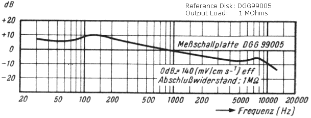
Fig. 2.1
Ceramics Pickup Cartridge
by
ELAC: BST 1 (1958)
[2.2]
Keramik-Tonabnehmer
.
|
.
Fig.
2.2 refers to a basic construction of piezoelectric pickup that was usually
supplied with low cost turntables. Most of these pickups have seignette
salt crystals based on potassium sodium tartrate. Regarding the disadvantageous
influence of temperature and humidity, however, ceramics instead of that
crystal compound does offer much better properties. Fig. 2.1 shows the
frequency response of a piezo-ceramic pickup made of barium titanate (BaTiO3).
Piezo-electric
pickup family usually does not need equalization as necessary for magnetic
types! Generally, crystal or ceramics cartridges deliver more output voltage
than magnetic ones. The difference is +30 to 40 db vs. MM types that usually
give out a few millivolts only at 1 kHz. Moving coil types typically do
less than 1 millivolt at that frequency.
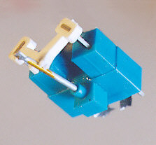
Fig.
2.2.1 shows a ceramic stereo pickup, as manufactured by RFT, Leipzig, Germany.
The support block (blue) is made of hard rubber, as well as the coupling
lever (white). The support block of cantilever (stylus rod) has its position
in the cartridge box which has been removed! |
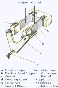 |
Fig.
2.2
Piezo-electric
Stereo Pickup.
Simple
example for construction [2.8].
|
Fig.
2.2.1 Modern Ceramic Pickup by RFT, East Germany. Photo by the author. |
.
Fig.
2.2 bezieht sich auf den grundsätzlichen Aufbau eines piezoelektrischen
Tonabnehmers, wie er üblicherweise mit Kristallelementen aus Seignettesalz
(Kaliumnatriumtartrat) für preiswerte Plattenspieler vorgesehen wurde.
Zum nachteiligen Einfluss von Temperatur und Luftfeuchtigkeit auf eine
solche Kristallverbindung bietet Keramik dagegen weitaus günstigere
Eigenschaften. Fig. 2.1 zeigt den Frequenzgang eines piezokeramischen Tonabnehmers
aus Bariumtitanat (BaTiO3).
Die
piezoelektrische Tonabnehmer- Familie benötigt üblicherweise
nicht die für Magnetsysteme erforderliche Entzerrung! Kristall- oder
Keramiktonabnehmer liefern in der Regel außerdem mehr Ausgangsspannung als magnetische
(+30 db ...40 dB gegenüber MM Version), welche nur wenige Millivolt
bei 1 kHz abgeben; MC -Typen (Moving Coil) liegen bei dieser Frequenz
üblicherweise noch unterhalb von einem Millivolt.
Fig.
2.2.1 zeigt einen Keramik- Stereotonabnehmer von
RFT
(Leipzig). Sowohl das Lagergehäuse als auch der Kopplungssteg bestehen
aus Hartgummi. Der Lagerblock vom Tonnadelträger befindet sich im
Tonabnehmergehäuse, das hier jedoch entfernt wurde.
|
How
to plug-in a Crystal or Ceramic Pickup
Unfortunately,
modern audio amplifiers have no special input jack for a piezo-electric
pickup! This is a very disadvantageous item since the AUX input usually
does not guarantee best audio performance in this case. However, reliable
adapter circuits have been introduced for using now the amplifier's magnetic
pickup input!
Fig.
2.2.2 reveals a 36 db T- Attenuator as well as a simple L-Type version
(27 db). Note well that such adapters must have a shielded case!
In
1958, Experts recommend to replace sapphire stylus of piezo- electric pickups
after circa 50 hours of usage, while magnetic or dynamic pickups are usually
supplied with longlife diamond stylus. |
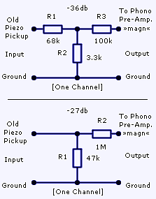
Fig.
2.2.2 Two adapter circuits for best setup.
|
Wie
schließt man einen Kristall- oder Keramik-Tonabnehmer an?
Leider
haben moderne Audio- Verstärker keine Eingangsbuchse für piezo-
elektrische Tonabnehmer! Dies ist insofern von Nachteil, als der AUX- Eingang
in diesem Fall für gewöhnlich nicht die best mögliche Wiedergabequalität
gewährleistet. Jedoch brachte man Anpassschaltungen heraus, die für
den Anschluss an den magnetischen Tonabnehmer- Eingang ausgelegt sind!
Fig.
2.2.2 enthüllt einen 36 dB T- Abschwächer sowie eine Ausführung
in Form eines einfachen L- Glieds (27 db). Solche Adapter benötigen
unbedingt ein abgeschirmtes Gehäuse!
Im
Jahr 1958 empfehlen Fachleute den Austausch des Saphirs von piezoelektrischen
Tonabnehmern nach circa 50 Betriebsstunden. Dagegen sind magnetische oder
dynamische Abnehmer in der Regel mit einer langlebigen Diamantnadel ausgestattet.
|
1959
| C.
R. Bastiaans makes a documentary report on different kinds of technical
pickups for Radio-Bulletin magazine [2.9]. The Funkschau
publishes a reprint from his detailed contribution in German language [2.10]. |
|
Der
links zitierte Autor erstellt eine Dokumentation über unterschiedliche
Arten von Tonabnehmern für das Radio-Bulletin Magazin [2.9].
Die Funkschau veröffentlicht einen Nachdruck seines detaillierten
Beitrages [2.10]. |
| This
illustration, Fig. 2.3.1, represents a piezo- electric system as manufactured
by Garrad company. A signal picked up from the inner flank of the groove,
as reserved for left channel, causes movement to direction as shown by
the unbroken arrow. Thus, the L- crystal slice will be imposed on lateral
bending stress which only can generate electric voltage at the crystal. |
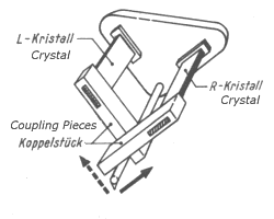
Fig.
2.3.1
|
Diese
Abbildung, Fig. 2.3.1, stellt ein piezo- elektrisches System dar, das von
der Firma Garrard produziert wird. Ein von der inneren Rillenflanke diese
ist für den linken Kanal reserviert abgenommenes Signal verursacht
die vom nicht unterbrochenen Pfeil gezeigte Bewegung. Dadurch wird der
L- Kristall mit einer seitlichen Biegespannung beaufschlagt; und nur diese
kann eine elektrische Spannung am Kristall hervorrufen. |
| Fig.
2.3.2 shows an improved popular construction with a rhombus of compliant
material for coupling device, as applied by British BSR, German DUAL, and
Dutch RONETTE companies. |
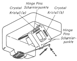
Fig.
2.3.2
|
Fig.
2.3.2 zeigt eine beliebte weiter entwickelte Konstruktion mit einer nachgiebigen
Raute als Koppler aus biegefähigem Material. Dieses System wurde von den
Firmen BSR, DUAL und Ronette (Holland) verwendet. |
| This
illustration, Fig. 2.3.3, is an exploded view to so- called 'Duplo Pickup'
for expired Normal format (mono) as well as Micro for stereo! Note that
#A will be clamped for stereo mode, while there will be motion to pivot
points #1, #3, and #2. However, #A will be laterally moved when playing
N 78 disks after a half revolution of this system. This refined pickup
has been also applied by aforesaid companies. |
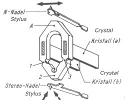
Fig.
2.3.3
|
Die
mit Fig. 2.3.3 gegebene Zeichnung ist eine Explosionsdarstellung eines
sogenannten Duplo- Systems für das abgelöste Normal-Mono- als
auch das Micro- Stereoformat. Punkt A hat feste Klemmung bei Stereobetrieb,
während 1, 3 und 2 Drehpunkte sind. Bei N 78 Monoplattenwiedergabe
(System um 180° gedreht) wird A jedoch seitlich bewegt. Dieses verfeinerte
System kam ebenfalls bei den vorgenannten Firmen zur Anwendung. |
| Philips
company prefers the so-called W-System, s. Fig. 2.3.4. The enclosed ends
of both crystal slices are linked with a flexible stripe. The broken arrow
represents force direction by right channel groove flank which accordingly
bends the corresponding crystal slice on the right. Position #1 indicates
pivot to this instance. |
| Die
Firma Philips bevorzugt das sog. W-System, Fig. 2.3.4. Die eingefass- ten
Enden beider Kristallplättchen sind durch einen elastischen Streifen
miteinander verbunden. Der unterbrochene Pfeil zeigt die Kraftrichtung
des rechten Kanalsignals, welche auf den zugeordneten Kristall (rechts)
einwirkt. Ziffer 1: Drehpunkt. |
|
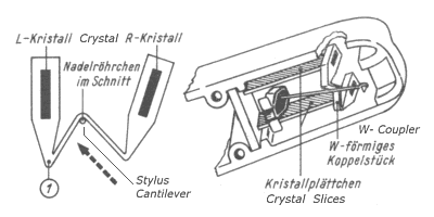 Fig.
2.3.4
.
 |
| The
American Columbia company favours this 'winged construction', Fig.
2.3.5. The black arrow shows motion direction of left channel signal which
may only cause force at #2. Point #3 will be virtual bending pivot to the
axis defined by #1 and #3. |
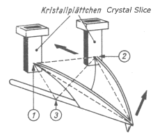
Fig.
2.3.5
|
Die
amerikanische Columbia favorisiert diese "geflügelte Konstruktion",
Fig. 2.3.5. Die Signalinformation des linken Kanals, deren Bewegungsrichtung
durch den schwarzen Pfeil gezeigt wird, verursacht eine Krafteinwirkung
an Punkt 2. Punkt 3 ist der virtuelle Drehpunkt zu der von den Punkten
1 und 3 gebildeten Achse. |
| Westrex,
USA, has developed a dynamic pickup as principally shown by Fig. 2.3.6.
The moving coils are fixed at the struts of both a compliant plastic bow,
#1, #2, and the stylus cantilever, #3 #4. Thus, this construction
is an example for MC pickup. |

Fig.
2.3.6
|
Westrex,
USA, hat einen dynamischen Tonabnehmer entwickelt, dessen Prinzipdarstellung
in Fig. 2.3.6 gezeigt wird. Die bewegten Spulen sind sowohl an den Streben
eines nachgiebigen Kunststoffbügels (1, 2) als auch an jenen der Nadelrute
(vgl. 3, 4) befestigt. Damit ist diese Konstruktion ein Beispiel für
einen MC- Tonabnehmer. |
| Another
refined dynamic pickup system presents Danish Ortofon company. Fig. 2.3.7
reveals that the cantilever has been fixed at a cube for special Cardanic
transmission. Points #1 and #2 mark the positions of the suspension pins.
Note that all magnetic system components have been omitted for demonstrating
only this so-called 'cross- coupler' which converts stylus deflection to
channel- separated rotary motion. |
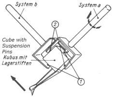
Fig.
2.3.7
|
Eine
andere ausgeklügelte Tonabnehmerkonstruktion präsentieret die
dänische Firma Ortofon. Wie Fig. 2.3.7 enthüllt, wurde die Nadelrute
für dieses kardanähnliche System an einem Würfel befestigt.
Punkte 1 und 2 markieren die Lagerstifte. Da hier nur das Prinzip dieses
sogenannten Kreuzkopplers der hier Nadelauslenkung in Rotationsbewegung
umwandelt dargestellt werden soll, wurden alle Komponenten für
das Magnetsystem ausgelassen. |
| American
Electrovoice company creates an impressing piezo- ceramic pickup as illustrated
by Fig. 2.3.8. Its valve is based on lead- circonate- titanate compound
(LCT). Numbers 1 to 4 mark the outer electrodes made of silver stripes,
whereas the concentric inner has been connected to ground. This polarized
valve has been simply coupled with rotary cantilever system that harbours
both mono and stereo stylus. |
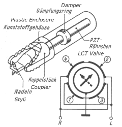
Fig.
2.3.8
|
Die
amerikanische Firma Electrovoice schafft einen eindrucksvollen piezokeramischen
Tonabnehmer, Fig. 2.3.8. Sein Keramikröhrchen ist aus Blei-Zirkonat-Titanat.
Die äußeren Elektroden bestehen aus Silberstreifen, während
die innere die gemeinsame Masse führt. Diese polarisierte Röhre
wurde einfach mit dem umschwenkbaren Nadelträger verbunden. Dieser
trägt sowohl eine Mono- als auch die Stereonadel. |
| Fig.
2.3.9 represents a less expensive electro- magnetic pickup made by General
Electric company, USA. The diagonally aligned pole pieces, standing in
orthogonal position to each other, do guarantee channel separation. |
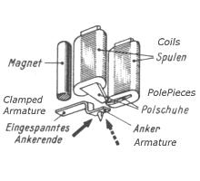
Fig.
2.3.9
|
Fig.
2.3.9 repräsentiert einen weniger aufwendig herzustellenden Tonabnehmer
von General Electric, USA. Die diagonal ausgerichteten und orthogonal zueinander
stehenden Polschuhe garantieren die Kanaltrennung. |
| Pickering
company refers to a solution which is quite related to construction of
General Electric Company. However, this variant by Pickering, Fig. 2.3.10,
has two pairs of pole pieces. (Note that only one of four coils appears
in this illustration.) The armature, to which also belongs the cantilever,
has been suspended at the magnet for pivot position. Thus, this pickup
system is based on more efficient push- pull mode. |
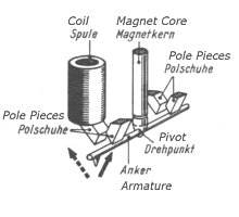
Fig.
2.3.10
|
Pickering
bezieht sich auf eine Lösung, die der von General Electric sehr ähnelt!
Die Pickering- Variante, Fig. 2.3.10, hat jedoch zwei Paar Polschuhe
nur eine von vier Spulen wird hier gezeigt. Der Anker ist gleichzeitig
Nadelträger und am Magneten drehgelagert. Dieses magnetische Aufnehmersystem
basiert somit auf dem effizienteren Gegentaktprinzip. |
| Fig.
2.3.11: This less expensive realization of dynamic MM pickup (Moving Magnet)
was favoured by American SHURE company as well as German ELAC, see also
Fig. 2.3.14. |
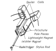
Fig.
2.3.11
|
Fig.
2.3.11: Diese weniger aufwendige Ausführung eines dynamischen MM-
Systems (Moving Magnet) wurde sowohl von den Firmen SHURE, USA, als auch
von der deutschen ELAC bevorzugt, siehe auch Fig. 2.3.14. |
| The
MC pickup by Fairchild, USA, shows Fig. 2.3.12. Both coils, diagonally
aligned and standing in orthogonal position to each other, are immovably
fixed at the cantilever. |
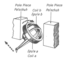
Fig.
2.3.12
|
Das
MC Tonabnehmersystem von Fairchild (USA) zeigt Fig. 2.3.12. Beide Spulen,
diagonal ausgerichtet und senkrecht zueinander stehend, sind mit dem Nadelträger
fest verbunden. |
| Neumann
company, Germany, offers this construction of dynamic moving coil pickup. |
| Die
Firma Neumann (Deutschland) bietet diese Konstruktion eines dynamischen
MC- Tonabnehmers an. |
|
 Fig.
2.3.13
 |
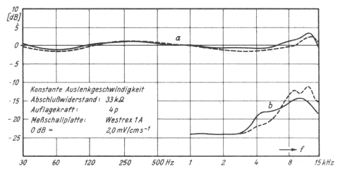 |
Frequenzgang
(Kurve a): 20Hz16000kHz +/- 2,5 dB Ausgangslast: 33 k Ohm Gestrichelt:
linker Kanal. Übersprechen: Kurve b Nadelauflagekraft: 3-5 pond Compliance:
4x10⁻⁶dyn/cm Nadelrundung: 15 ... 18 µm Dyn./Effektive
Masse:2,15mg Impedanz: 1480+j0,65 Ohm Ausgangsspannung p. Kanal: 20 mV
bei 10 cm/s Schnelle Gewicht: 12 g |
|
Fig.
2.3.14 ELAC Series STS 300
[2.11]
.
|
|
Technical
diagram of a pickup as based on Fig. 2.3.11.
|
|
Curve
pair a shows frequency response at an output load of 33 kOhms and stylus
force of 4 p. Broken line: Left channel.
|
|
Curve
pair b shows crosstalk.
|
|
Compliance:
4x10⁻⁶ cm/dyn. Rounding of spherical stylus: 15-18 µm.
Dynamic Mass: 2.15 milligrams. Weight: 12 grams
|
|
Electrical
impedance per coil: (1480 + j 0.65) Ohms. Output Voltage per channel:
20 mV at rapidity of 10 cm/sec.
|
|
.
|
| |
1961
.

Fig. 2.4
Frequency Response of
Shure M212.
Reference Disks: Electrola
EKL-35 and RCA 12-5-71.
.
|
.
In
1961, Shure Company presents a pickup unit, a tone arm supplied with a
magnetic cartridge, whose technical data might impress even today's users.
See Fig. 2.4 for frequency response diagram. This product, the M212, was
basing on the company's long experience of making phonographic appliance.
Technical
Data:
Frequency
Response:
20-20,000
Hz ±2.5 db Crosstalk: < - 20 db
Compliance:
9x10⁻⁶cm/dyn
Stylus
Force: 1.5-2.5 p
Dyn.
Mass: 1.3 milligrams. Diamond Stylus:
spherical
17µm
Output
Voltage: 4.5 mV at 1kHz
. |
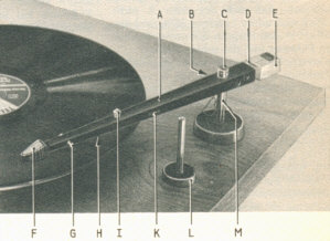 Fig
2.5
Shure
M212.
All
data and both illustrations by [2.1].
|
.
Im
Jahr 1961 ist mit dem aus langjähriger Mono- Tonabnehmer- Herstellung
gewonnenen Technologie- Stand der Firma Shure eine Tonarmeinheit lieferbar,
deren technische Daten aus damaliger wie heutiger Sicht sicherlich enorm
beeindrucken. Fig. 2.4 zeigt den Übertragungsbereich.
Technische
Daten:
Frequenzbereich:
20-20.000
Hz ±2,5 dB Übersprechen: < - 20 dB
Compliance:
9x10⁻⁶cm/dyn
Nadeldruck*:
1,5-2,5 pond
Dyn.
Masse: 1,3 mg Diamantnadel:
Rundungsradius
17µm
Ausgangsspannung:
4.5 mV bei 1kHz
Einführungspreis
in Deutschland: 404,15 DM
*:
Originalzitat (auch ff.); besser: Nadelauflagekraft |
.
A
New Semiconductor Phono Transducer is introduced by John F. Wood in
"Electronic Worlds" on Feb. 1965, P.50. The manufacturer is Euphonics Corp.,
USA, that offers this pickup system for nearly 80 US-$. The U-15 type has
one silicon chip (63 x 63 x 5 mil) per channel that converts change of
pressure to change of resistance. This is its excellent technical data
of that time:
Frequency
Response:
0-30,000
Hz ±2 db
Crosstalk:
< - 25 db
Compliance:
20
x10-6cm/dyn (s.Tab. 2.1)
Stylus
Force: 0.75-3 pond
Weight:
2 grams
Diamond
Stylus:
biradial/elliptical 5x23 µm
Output
Voltage: max. 80 mV at 20 V Supply (Feeding current: 10 mA).
In
the same year the audio expert F.A. Loescher tests some pickup
cartridges of remarkable reputation [2.3].
Classification:
1
Shure V15
2
Ortofon SPU-TE and ADC-4E
3
Pickering V15AME1 a. Shure M44-7
. |
1965 |
.
Die
Funkschau
Nr. 22 berichtet anhand des links zitierten Beitrags über ein Halbleiter-
Tonabnehmersystem, das die in den USA ansässige Firma Euphonics Corp.
für circa 80 US-$ anbietet. Dieses U-15 genannte System besitzt je
einen Siliziumchip pro Kanal in den Abmessungen 1,6 x 1,6 x 0,13 mm und
wandelt Druckänderungen in entsprechende Widerstandsänderungen
um.
Das
System hat diese für damalige Verhältnisse exzellenten Daten:
Frequenzbereich:
0-30.000 Hz ±2 dB
Übersprechen:
< - 25 dB
Compliance:
20 x10-6cm/dyn
(s.Tab. 2.1)
Nadelauflagekraft:
0,75-3 pond
Gewicht:
2 g
Diamantnadel:
biradial 5x23 µm
Ausgangsspannung:
max. 80 mV bei 20 V Betriebsspannung (Speisestrom: 10 mA).
Der
Audioexperte F.A. Loescher führt im gleichen Jahr
Tests an einigen Tonabnehmern von bemerkenswertem Ruf durch [2.3].
Rangfolge:
1
Shure V15
2
Ortofon SPU-TE und ADC-4E
3
Pickering V15AME1 u. Shure M44-7
. |
|
Manufacturer
|
Type
|
Weight [grams]
|
Compliance [10-6cm/dyn]
hor. vert.
|
Dynamic Mass
[milligram]
|
Vertical Pitch
|
Stylus Form
|
Stylus Rounding [µm]
|
Stylus Force [pond]
|
Output at R=5cm/sec
|
Crosstalk
[db]
|
|
Shure
|
V15
|
11
|
25 25
|
|
15°
|
biradial
|
5 / 22.5
|
0.8 - 1.5
|
6mV at 50k0hms
|
> - 25
|
|
Ortofon
|
SPU-TE
|
17
|
10 10
|
1
|
20°
|
biradial
|
5 / 30
|
2
|
10mV at 50k0hms
|
> - 25
|
|
Audio Dynamics
|
ADC- 4E
|
6
|
30 30
|
0.8
|
15°
|
biradial
|
5 / 30
|
0.8 - 1.5
|
8mV at 50k0hms
|
> - 22
|
|
Pickering
|
V15 AME1
|
5
|
13 10
|
|
15°
|
biradial
|
5 / 30
|
0.8 - 3
|
6mV at 50k0hms
|
> - 22
|
|
Shure
|
M44 -7
|
7
|
20 20
|
|
15°
|
spherical
|
15 - 18
|
1.5 - 3
|
5mV at 50k0hms
|
> - 24
|
|
Sonotone
|
9 TAHC
|
2.8
|
13
|
2.5
|
|
spherical
|
15 - 18
|
1 - 3
|
0.2V at 2M0hms
|
> - 20
|
|
Connoisseur
|
SCU-1
|
7.5
|
10
|
1
|
|
spherical
|
15 - 18
|
1.5 - 3
|
0.3V at 2M0hms
|
> - 20
|
|
Schumann
|
STC 481
|
4
|
8
5
|
2.4
|
12°
|
spherical
|
15 - 18
|
2 - 4
|
0.15V at 2M0hms
|
> - 15
|
Tab.
2 .1 [2.3]
|
Dynamic / Magnetic
Type
|
|
Ceramic Type
|
|
1N
= 105 dyn 1cm = 0.01m
| Notes: |
| biradial
= elliptical |
| Stylus
Rounding originally quoted 5 / 30 for Shure V15 has been corrected. |
| Anmerkungen: |
| Vertical
Pitch = vertikaler Nadel-Anstellwinkel |
| Angegebene
Ausgangsspannungen bei s = 5 cm/s. |
| Für
Shure V15 zitierte Nadelgeometrie (Rundung 5 / 30) wurde korrigiert. |
. |
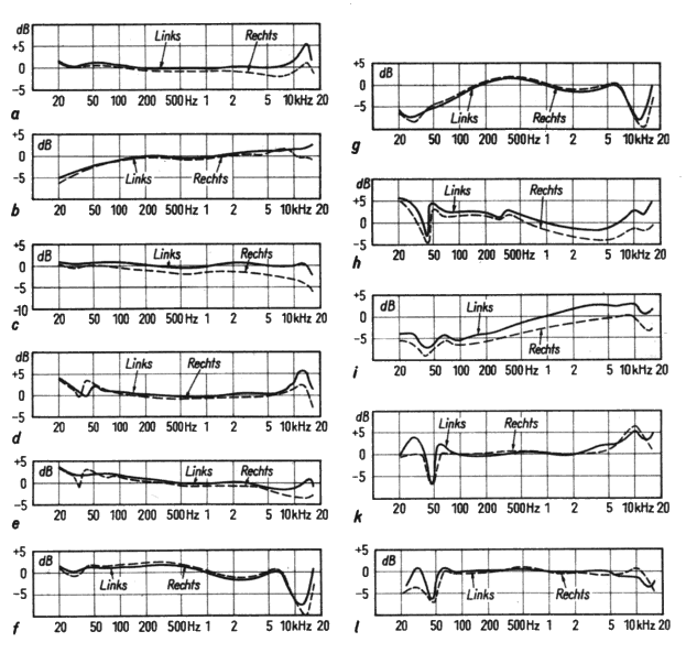
| |
Fig.
2.6
Frequency
Response Diagrams (Links = Left Channel; Rechts = Right Channel)
Frequenzdiagramme.
|
|
a
|
Shure
V15 |
|
b
|
Ortofon
SPU-TE |
|
c
|
Audio
Dynamics ADC-4E |
|
d
|
Pickering
V15 AME1 |
|
e
|
Shure
M44 -7 |
|
f
|
Sonotone
9 TAHC |
|
g
|
Sonotone
9 TAHC, output load 1 MOhms |
|
h
|
Connoisseur
SCU -1 |
|
i
|
Connoisseur
SCU -1 plus pre-amplifier for MM system (input load: 50 kOhms) |
|
k
|
Schumann
STC 481 |
|
l
|
Schumann
STC 481 plus RC correction filter plus pre-amplifier for MM system (input
load: 50 kOhms) |
.
Technical
Data of Shure Products, 1965 [2.4]
..
|
Shure Type
|
. |
M44-5 |
M44-7 |
M55-E |
V15 |
Frequency
Response
Frequenzbereich |
Hz |
20
- 20 000 |
20
- 20 000 |
20
- 20 000 |
20
- 20 000 |
Output
Voltage (1 kHz)
Ausgangsspannung |
mV |
6 |
9 |
6 |
6 |
Channel
Separation
Kanaltrennung |
db |
>
25 |
>
25 |
>
25 |
>
25 |
Cartridge
Load
Abschlusswiderstand |
k0hms |
47 |
47 |
47 |
47 |
| Compliance |
cm/dyn |
25x10-6 |
25x10-6 |
25x10-6 |
25x10-6 |
Stylus
Force
Nadelauflagekraft |
pond |
0.75
- 1.5 |
1.5
- 3 |
0.75
- 1.5 |
0.75
- 1.5 |
Inductivity
per Channel
Induktivität
pro Kanal |
mH |
680 |
680 |
680 |
680 |
DC
Resistance p.Channel
Wicklungswiderstd.p.K. |
0hms |
650 |
650 |
650 |
650 |
Stylus
Rounding
Nadelverrundung |
µm |
13 |
18 |
22.5x5 |
22.5x5 |
Tab.
2.2
.
.
Philips,
Netherlands, introduces a High Fidelity ceramic pickup cartridge with
renewed transducer material: The compound for GP 233 product is lead- titanate-
circonate: PbTiZrO3.
This
development largely excels barium titanate based ceramic pickups. However,
this pickup system will need a pre- amplifier.
Technical
Data GP 233:
Ceramic
Resonant Frequency:
100
kHz...1 MHz (!)
Frequency
Response:
30-17,000
Hz ±2 db Crosstalk: < - 24 db
Compliance:
8x10⁻⁶cm/dyn
vertical: 6.5x10⁻⁶cm/dyn
Stylus
Force 1.5 -2 pond
Dyn.
Mass: 2 grams
. |
1968
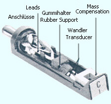
Fig.
2.7.
Philips
GP 233
|
Der
Philips Konzern stellt sein erneuertes High Fidelity Tonabnehmersystem
mit der Bezeichnung GP 233 aus Blei-Titan-Zirkonat Keramik vor (PbTiZrO3).
In
seinen übertragungstechnischen Eigenschaften übertrifft diese
Entwicklung deutlich die auf Bariumtitanat basierenden Tonabnehmer. Es
wird jedoch ein Phono- Vorverstärker benötigt.
Technische
Daten GP 233:
Resonanzfrequenz
der Keramik:
100
kHz...1 MHz (!)
Frequenzbereich:
30-17.000
Hz ±2 dB
Übersprechen:
< - 24 dB
Compliance:
8x10⁻⁶cm/dyn
vertikal: 6,5x10⁻⁶cm/dyn
Nadelauflagekraft
1,5 -2 pond
Dynamische
Masse: 2 Gramm
. |
.
At
German HiFi fair '68, Dusseldorf, Japanese Thoshiba company presents a
much impressing optical pickup cartridge, the C-100P type as represented
by Fig. 2.8.
This
innovation is not typically based on generator principle, as Fig. 2.9 does
demonstrate accordingly. The cantilever is fixed at the rubber plate that
maintains viscous resistance for compliance and absorbing. The fixed screen
as well as the moving shutter are slit. The photo transistors have extremely
focussed lens.
The
designers could reduce harmonic distortion to less than 0.65% at 1 kHz,
cf. Fig. 2.10. The rating of the 2 Volts filament lamp will be circa 10,000
hours. The large size of the cartridge, as shown by the photo, is a result
of sink function for the lamp's heat!
This
optical pickup has an enormous transmission parameter of 14.5 mVs/cm, respectively
40 mVs/cm per channel at the output of its pre- amplifier.
Technical
Data by manufacturer:
Frequency
Response:
20-40,000
Hz
Crosstalk:
< - 32 db
Compliance:
30 x10-6cm/dyn
Stylus
Force: 0.5-1.7pond
Dyn.
Mass: 0.3 milligram.
Weight:
11.5 grams
Diamond
Stylus:
birad./elliptical
7.6x20.3 µm
Reference:
[2.5].
|
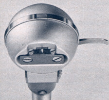 Fig.
2.8.
.
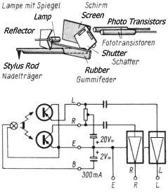 Fig.
2.9.
.
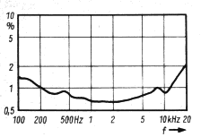
Fig.
2.10.
|
.
Auf
der Düsseldorfer HiFi Messe stellt die japanische Firma Toshiba einen
recht beeindruckenden optischen Tonabnehmer vor, den C-100P, wie im Foto
Fig. 2.8 dargestellt.
Diese
Innovation beruht nicht auf dem typischen Generatorprinzip, wie Fig. 2.9
entsprechend ausweist. Der Nadelträger ist an einem Gummifederplättchen
befestigt, welches den viskosen Widerstand für die Compliance
(Nadelnachgiebigkeit und Dämpfung) herstellt. Sowohl der unbewegliche
Schirm als auch der sogenannte Schatter (bewegte Schlitzblende) sind geschlitzt.
Die Fototransistoren verfügen über eine stark bündelnde
Optik.
Die
Entwickler konnten den Klirrfaktor unter 0,65% bei 1 kHz halten, vgl. Fig.
2.10. Die Lebensdauer der 2 V Glühfaden- Lampe soll ca. 10.000 Stunden
betragen. Das große Gehäuse des Tonabnehmers (Foto) wurde für
die Ableitung der Lampenwärme bemessen!
Dieser
optische Tonabnehmer hat einen enorm hohen Übertragungsfaktor von
14,5_mVs/cm,
beziehungsweise 40_mVs/cm
pro Kanal an seinem Vorverstärkerausgang.
Technische
Daten vom Hersteller:
Frequenzbereich:
20-40.000
Hz
Übersprechen:
< - 32 dB
Compliance:
30 x10-6cm/dyn
Nadelauflagekraft:
0,5-1,7 pond
Dyn.
Masse: 0,3 mg
Gewicht:
11,5 g
Diamond
Stylus:
biradial/elliptisch
7,6x20,3 µm
Quelle:
[2.5]. |
Shure
company improves trackability of M75 pickup cartridges [2.6]. The company's
best pickup, V15 II, can handle now rapidity of 35 cm/sec.
. |
1970 |
Die
Firma Shure verbessert das Abtastverhalten der M75 Tonabnehmer [2.6]. Ihr
bestes System V15 II beherrscht jetzt eine Schnelle von 35 cm/s.
. |
|
Type
|
Dynamic
Mass
Effektive
Masse
[x
0.001 kg]
|
Stylus
Form
Nadelausführung
|
Stylus
Force
Nadelauflagekraft
[pond]
|
Max.
Rapidity
Max.
Schnelle
[cm/sec]
(1 kHz)
|
|
M75
-6 Type2
|
0.6
|
spherical
|
1.5
- 3
|
28
|
|
M75
-G Type2
|
0.6
|
spherical
|
0.75
- 1.5
|
28
|
|
M75
-E Type2
|
0.6
|
biradial
|
0.75
- 1.5
|
28
|
|
M75
-EJ Type2
|
0.6
|
biradial
|
1.5
- 3
|
35
|
Tab.
2.3
.
Matsushita,
Japan, has made use of strain gauge for a new pickup system. Sescosem,
a French company, takes pattern from this development and presents a sophisticated
application basing on a silicon gauge coupled with a MOS transistor device.
This pickup will deliver 200 mV output voltage per channel within a frequency
range of 0-30,000 Hz. The dynamic mass was quoted 0.7 milligram at a compliance
of 10x10-6 cm/dyn for a stylus force of 0.75 pond. However,
it has been proposed to improve this development for the S/N ratio of only
40 db; [2.7].
. |
|
Matsushita,
Japan, verwendet einen Dehnungsmessstreifen (DMS) für einen neuartigen
Tonabnehmer. Das französische Unternehmen Sescosem greift diese Entwicklung
auf und präsentiert eine verfeinerte Anwendung mit einem Siliziumstreifen
in Kopplung mit einem MOS- Transistorschaltkreis. Dieser Tonabnehmer soll
eine Ausgangsspannung von 200 mV pro Kanal liefern. Sein Frequenzbereich
wird mit 0-30.000 Hz angegeben. Die effektive (dynamische Masse) dieses Systems
beträgt 0,7 mg (Compliance: 10x10-6 cm/dyn) für einen
Nadeldruck von 0,75 pond. Der Geräuschspannungsabstand von lediglich
40 dB ließ diese Entwicklung jedoch verbesserungswürdig erscheinen;
[2.7].
. |
2004
audio-technica
CN5625AL |
| This
low-cost MM cartridge made by audio-technica is a much popular ''aftermarket
product' which is offered for circa 30 US-$ by an American retailer (April
2004). The CN5625AL can easliy replace many other cartridges by its 1/2"
two hole standard mount system.
Technical Data (Quotation):
Frequency
Response:
20-20,000
Hz
Linearity:
No data by manufacturer publication.
Channel
Separation: 20db (1kHz)
Channel
Balance: 1.5db
Stylus
force: 1.5-2.0grams
Stylus
form: conical (0.7mil)
Output
voltage: ca. 4mV at 1kHz and a rapidity of 5cm/sec |
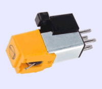
Fig.
2.11
|
Dieses
preiswerte MM Magnetsystem von audio-technica ist ein beliebtes sog. "Aftermarket"-
Produkt, das ein Lieferant in den USA für ca. 30 US-$ dem Endverbraucher
anbietet (April 2004). Durch seine 1/2" Zweiloch- Befestigung kann das
CN5625 viele andere Magnetsysteme problemlos ersetzen.
Technical Daten (Zitat):
Frequenzbereich:
20-20.000
Hz
Linearität:
keine Herstellerangabe
Kanaltrennung:
20dB (1kHz)
Kanalabweichung:
1.5dB
Nadelauflagekraft:
1.5-2.0 p
Nadelform:
konisch (0.7mil)
Ausgangsspannung:
ca. 4mV bei 1kHz und 5cm/sec Nadelschnelle |
.
Fig.
2.12 & 2.13 are photos of an opened magnetic pickup made by Audio
Dynamics (ADC), USA.
Each
channel has two coils which are linked crosswise. Their pole pieces are
diagonally falling into the inlet for the cantilever.
(US
Patent 3 294.405)
Fig.
2.11 & 2.12 sind Fotos von einem geöffneten Magnetsystem von Audio
Dynamics (ADC), USA.
Jeder
Kanal hat zwei kreuzweise verbundene Spulen, deren Polbleche diagonal im
Nadelträger- Kanal münden.
(US
Patent 3 294.405). |
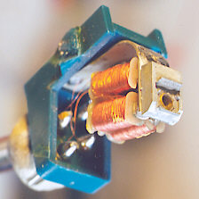
Fig.
2.11
Photos
by the author.
|
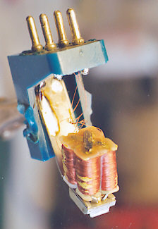
Fig.
2.12
|
.
Specifications
: URLs of popular cartridge & pickup brands
In
alphabetical order.
April
2004.
| Name |
Internet
URL |
Cartridge
products
[Some
models possibly have expired.] |
| ADC |
http://www.adelcom.net/ADCCart1.htm |
all |
| audio-technica |
http://www.audio-technica.com/guide/other/styli/cart.html |
all |
| Dynavector |
http://www.dynavector.com/dvcarts.htm |
all |
| Goldring |
http://www.mantra-audio.co.uk/goldring_cartridge_technical_data.html |
all |
| Ortofon |
http://www.ortofon.com/html/body_moving_coil_technical_data.html |
moving
coil cartridges |
|
http://www.ortofon.com/html/body_magnetic_technical_data.html |
moving
magnet cartridges |
| Pickering |
http://www.pickeringuk.com/spex.html |
all |
| Shure |
http://www.shure.com/v15vxmr.html |
V15VxMR |
|
http://www.shure.com/m97xe.html |
M97xE |
|
http://www.shure.com/m92e.html |
M92E |
| Other
(retailer): |
http://www.moving-coil-cartridges.com/ |
|
Errors
and omissions excepted!
Irrtum
und Auslassungen vorbehalten!
|
back
to top |
.
|
References
Quellen
[2.1] Funkschau 1961, Nr.18, S.473.
[2.2] Funkschau 1958, Nr.21, S.489.
[2.3] Funkschau 1965, Nr.15, S.411-414.
[2.4] Funkschau 1965, Nr.10, S.264.
[2.5] Funkschau 1969, Nr. 2, S.99-100.
[2.6] Funkschau 1970, Nr.5, S.148.
[2.7] Funkschau 1970, Nr.12, S.376.
[2.8] Funkschau 1958, Nr.11, S.273
[2.9] Radio-Bulletin 1959, No. 7.
[2.10]
Funkschau 1960, Nr.9, S.487-488.
[2.11]
Funkschau 1959, Nr.9, S.209.
. |
|

